BIM in-depth design
Detailed design of steel structure joint
1. Determine the principle of in-depth design
Principle 1: principles to be abided by in-depth design of steel structure
Prevent lamellar tearing of thick plates; prevent overlapping of welds; pay attention to the deepening of column end milling; pay attention to the deepening of over welding holes; pay attention to the setting of lifting lugs (or positioning connecting plates).
Principle II: coordination principle for connection with civil structure construction
During the detailed design, it is necessary to consider the studs that are not easy to be welded on the site; the connectors that may be needed to fix the formwork; the cavities that need to be opened for the grouting of the steel column base plate; the steel supports (both permanent and temporary) that need to be added for the concrete construction of the floor slab, etc.
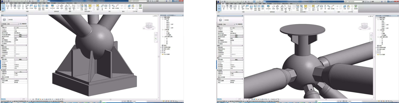
In the mixed structure of circular pipe column, box column and cross steel column concrete, the intersection between steel column and concrete component is more prominent. During the detailed design and modeling, all the steel bars are set out. According to the structural requirements of steel bars and beam column joints, the relationship between the two is reasonably handled by comparing the three-dimensional solid model.
Principle 3: cooperation with mechanical and electrical equipment, curtain wall and decoration
Attention shall be paid to the reserved holes for the mechanical and electrical pipelines passing through the steel members and the reinforcement measures for the openings; consideration shall be given to the connectors to be preset; consideration shall be given to the plates to be connected with the steel structure for the equipment base; consideration shall be given to the plates to be temporarily connected with the steel structure for the equipment hoisting; consideration shall be given to the connections and fixed plates between the elevator system and the steel structure; consideration shall be given to the connections and fixed plates between the curtain wall system and the decoration works and the steel structure Parts, holes, etc., to ensure that steel structure holes and hole reinforcement are carried out in the factory to ensure the quality of the project
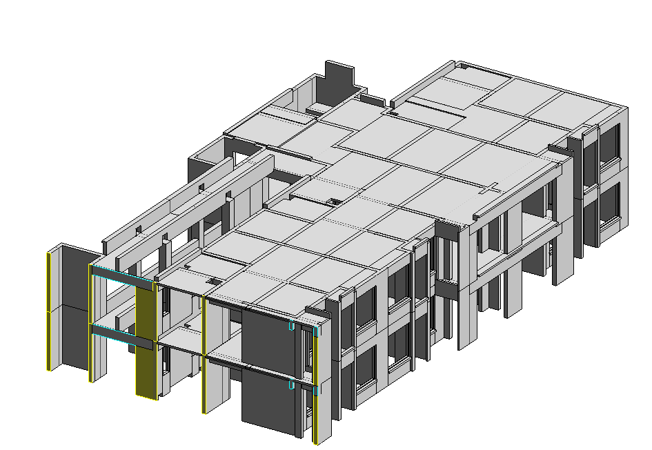
2. Structure Deepening BIM model creation process
① Based on the steel structure construction drawing issued by the designer, the BIM model is created by using Revit software, Tekla structures software or ProStructures software to design the steel structure detail and intelligent node.
②According to the component layout, component section, main node structure and various relevant data and technical requirements provided in the construction drawing, strictly abide by the relevant design specifications and drawings of steel structure, and improve the component structure.
③According to the factory manufacturing conditions and site construction conditions, and considering the transportation requirements, lifting capacity and installation factors, determine the reasonable component unit.
3. Cross coordination with other disciplines Work together with BIM team of civil engineering, mechanical and electrical engineering, curtain wall and other disciplines to integrate the created BIM model of steel structure with BIM model of civil engineering, mechanical and electrical engineering, curtain wall and other disciplines, carry out collision inspection, find and solve problems in component collision, processintersection, connection and cooperation among disciplines in advance, reduce design changes and engineering rework caused by the above reasons, and work for the project At the same time, it provides the basis for the overall construction schedule of the project and the construction schedule of steel structure discipline.
4. Output drawing processing drawing and construction drawing
With the professional steel structure deepening design drawing software, the overall form of the component, the dimensions and requirements of each part in the component and the connection methods between the parts are shown in the drawings in detail, so that the manufacturing and installation personnel can clearly
understand the structural requirements and design intent through checking the drawings, and complete the processing and production of the components in the factory and the assembly and installation on site.

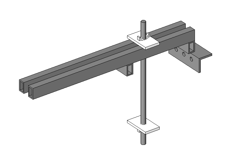
Electromechanical integrated support
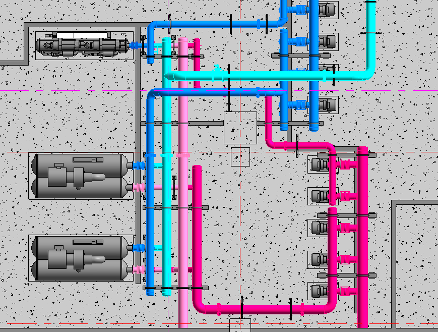
1. Determine the layout plan of electromechanical integrated pipeline, and establish a three-dimensional BIM model between disciplines.
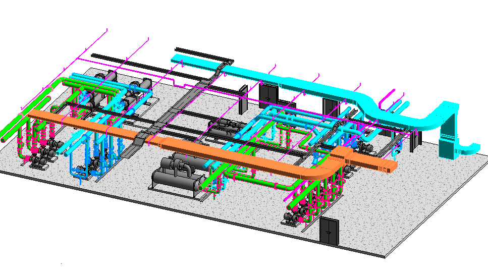
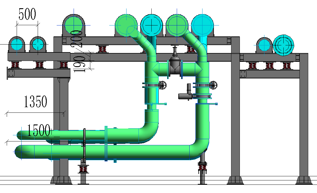
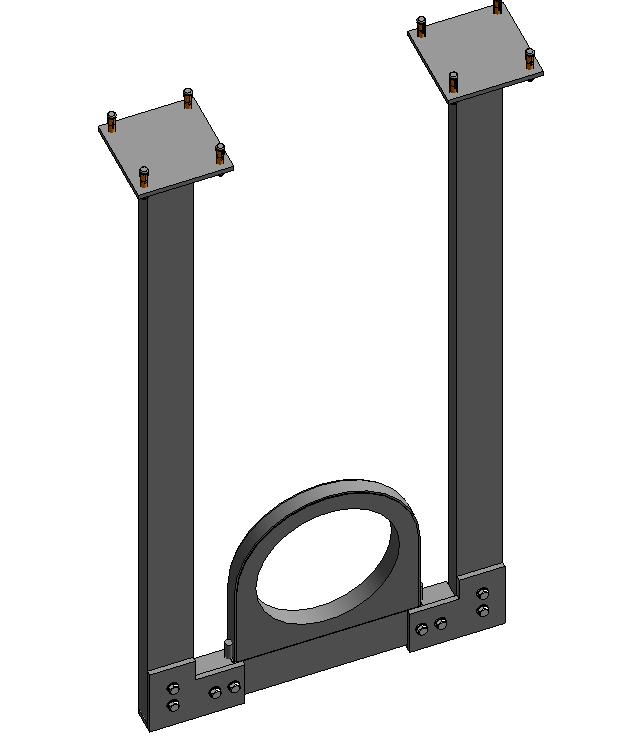
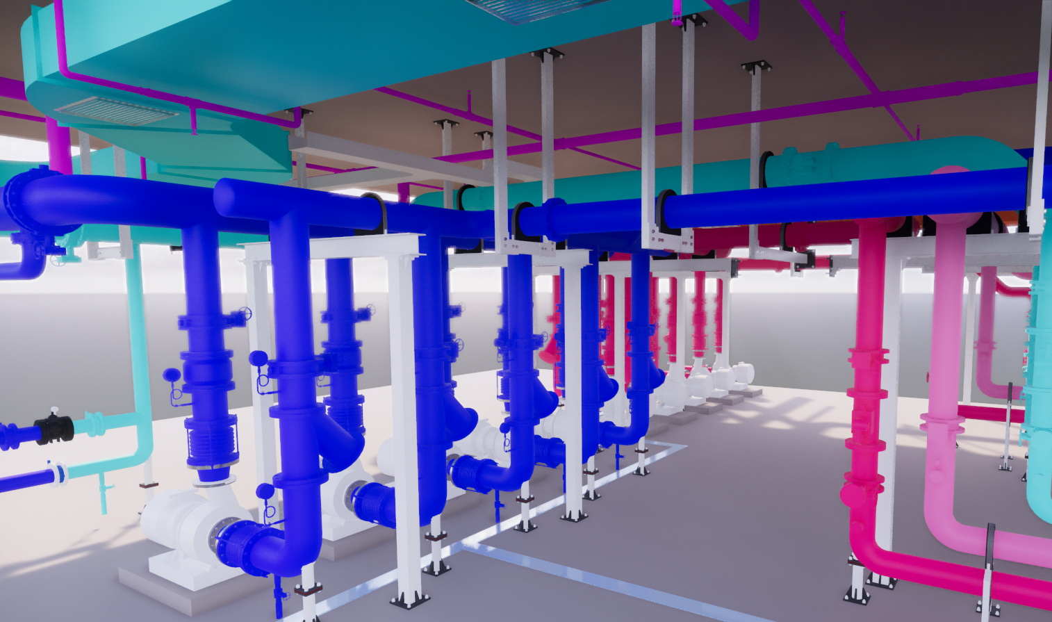
2. Make a comprehensive support design scheme, create a three-dimensional model of the comprehensive support, and integrate the mechanical and electrical model with the support model.
3. Use the stress analysis software to analyze, calculate whether it meets the specification requirements, and then adjust.
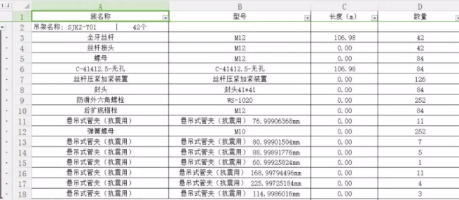
4. Export calculation sheet and make statistics of bill of quantities.
5. Prepare the construction drawing of comprehensive support, export the three-dimensional model file, and conduct the visual disclosure of on-site construction.
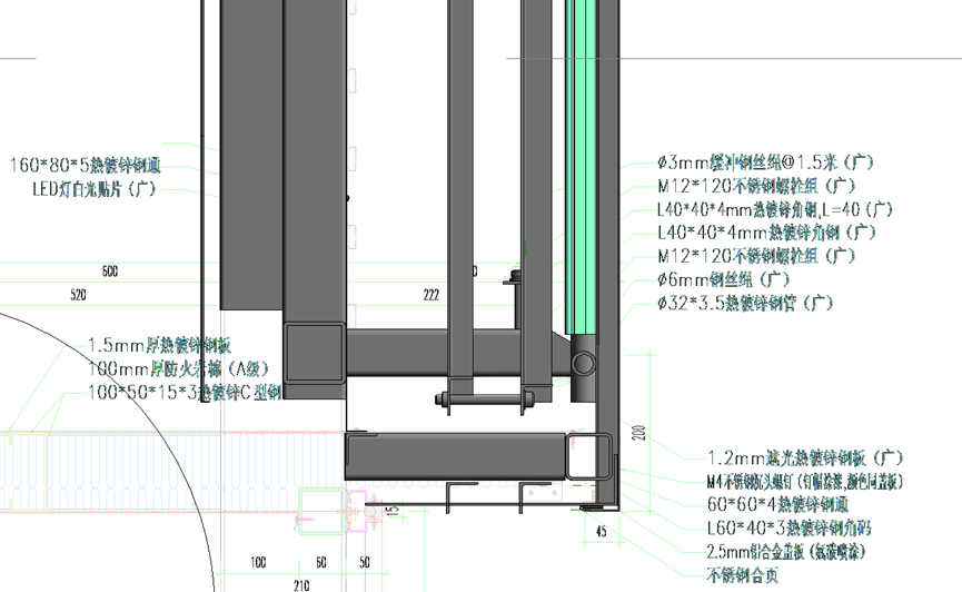
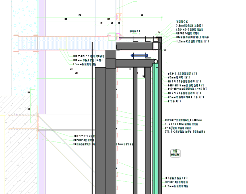
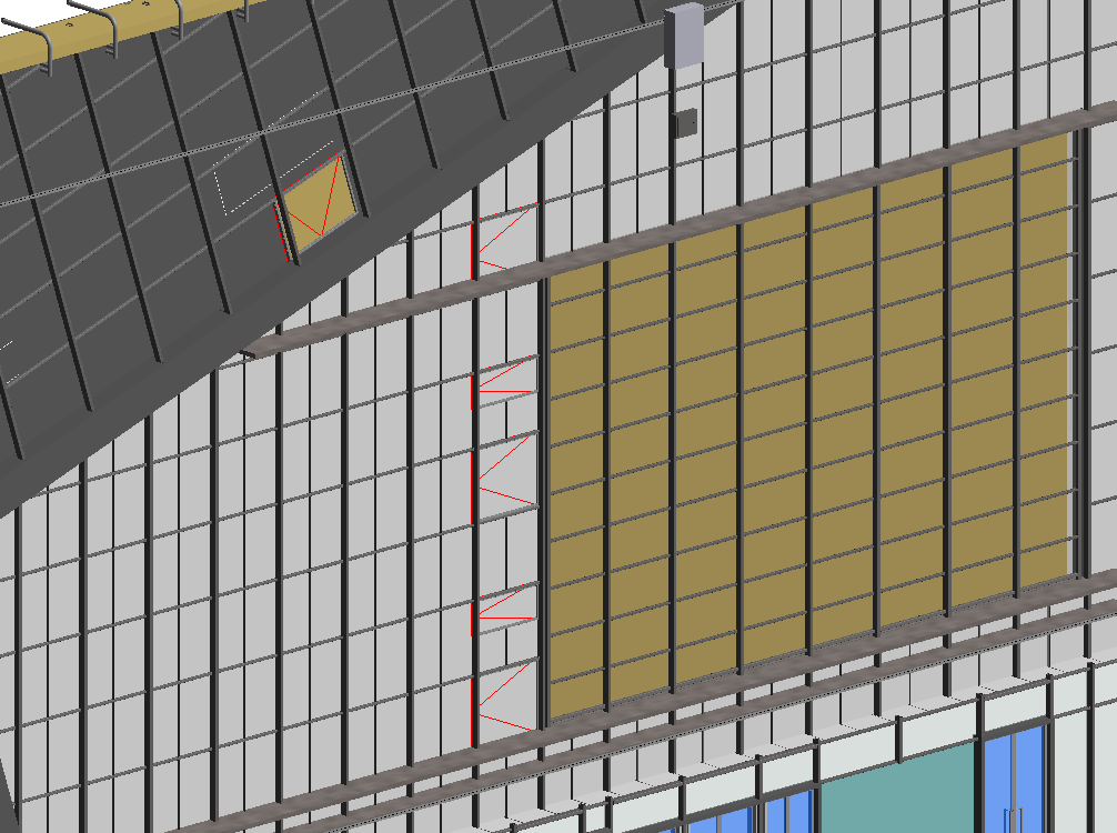
Curtain wall deepening design
Through the creation of BIM 3D model, the method of accurately and intuitively expressing curtain wall nodes can solve the difficulties in the construction process, reduce the errors and a large number of repeated work on the basis of 2D drawings, and greatly save the construction period.
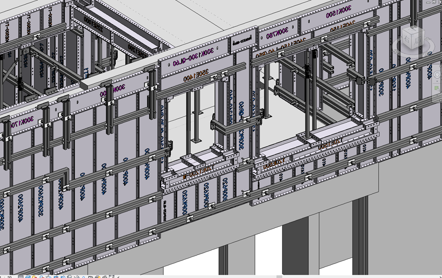
Aluminum mold deepening
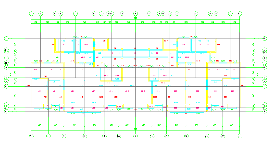
1. Determine the preliminary two-dimensional layout scheme of the template and establish the preliminary three-dimensional BIM model of the structure.
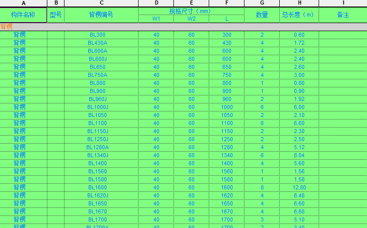
2. According to the relevant specifications, collect the relevant site template pictures, and establish the aluminum mold related accessories family. Such as: plate back edge and screw.
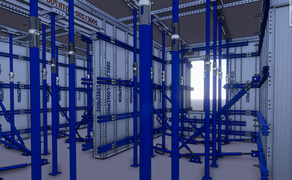
3. Establish and pre assemble the aluminum mold model, and number and code it.
4. Draw two-dimensional construction drawings from three dimensions and make statistics of bill of quantities.

5. Deliver to the site, conduct construction simulation and guide the site construction.
 中文
中文 English